Tennis Court Light Poles
- Steel, aluminum, and composite fiberglass pole options available
- Selection support for court layout and fixture mounting
- Direct-burial and anchor-base configurations offered



Our Tennis Court Light Poles include steel, aluminum, and composite fiberglass poles for outdoor court lighting systems. Available configurations include direct-burial and anchor-base poles, with options for fixtures, brackets, crossarms, wiring, and other mounting equipment. Decorative finishes include bronze-colored, black, green, and other architectural finishes.
These poles are used for outdoor recreational courts, school facilities, athletic clubs, community parks, multi-court tennis complexes, and adjacent tennis court layouts.
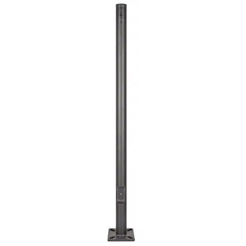

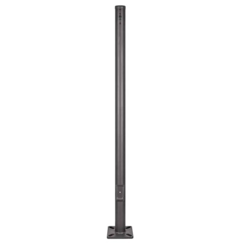





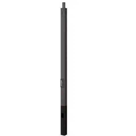
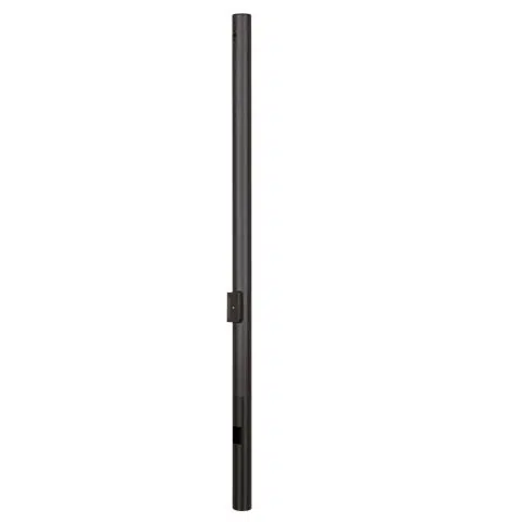
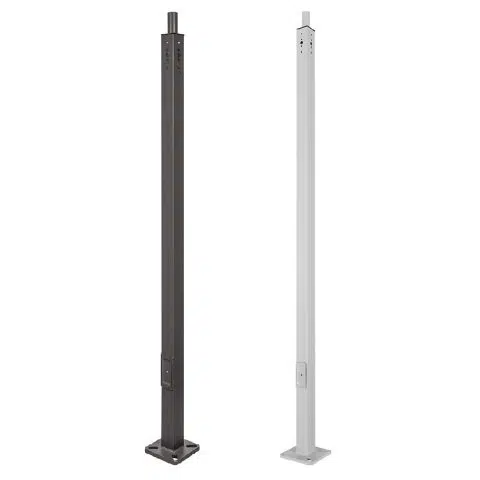
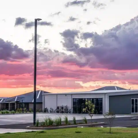
Tennis court light poles support the fixtures, brackets, crossarms, wiring, and mounting equipment used to illuminate outdoor recreational courts, school facilities, athletic clubs, community parks, and multi-court tennis complexes. The correct pole system depends on the court dimensions, number of courts, available sideline setbacks, above-grade mounting height, fixture arrangement, allowable EPA, wind requirements, installation method, soil conditions, surrounding properties, and photometric plan.
Depending on project requirements and availability, options may include steel light poles, aluminum poles, and composite fiberglass light poles. Each material has different structural, corrosion, installation, mounting, deflection, finish, and maintenance considerations.
For fixture selection, light levels, uniformity, optics, glare control, color temperature, controls, and detailed application guidance, visit our tennis court lighting page.
Selection Note: Tennis court poles should not be selected using pole count, height, material, or fixture wattage alone. Court dimensions, pole setbacks, player sight lines, fixture quantity, mounting configuration, allowable EPA, wind criteria, foundation or embedment, and photometric results should be evaluated together.
How to Select Tennis Court Light Poles
Start with the court layout, available pole locations, setbacks, and lighting plan. Then compare pole height, material, fixture mounting arrangement, allowable EPA, installation method, foundation or embedment requirements, and site conditions for each pole position. The sections below explain layout options, materials, mounting, installation, and photometric coordination in more detail.
| Selection Factor | What to Confirm |
|---|---|
| Court dimensions | Provide the playing-area dimensions, court orientation, baselines, sidelines, doubles alleys, run-off areas, fences, gates, spectator areas, walkways, buildings, and nearby property limits. |
| Number and arrangement of courts | Identify whether the project includes one court, adjacent courts, back-to-back courts, or a larger tennis complex. Shared pole locations may affect fixture quantity, aiming, glare, wiring, EPA, and foundation demand. |
| Facility use | Confirm whether the courts support residential recreation, parks, schools, clubs, leagues, organized competition, training, or spectator events. Required lighting criteria should be confirmed with the facility owner or governing organization. |
| Project location | Provide the installation address so pole options can be compared with wind exposure, terrain, frost conditions, soil, moisture, salt exposure, and other site factors. |
| Pole locations and setbacks | Confirm available positions along the sidelines and between courts, including player-clearance areas, fences, gates, bleachers, walkways, utilities, roads, parking areas, and neighboring properties. |
| Mounting height | Select the above-grade mounting height using court dimensions, pole count, setback, fixture output, optics, aiming, glare goals, maintenance access, local restrictions, and photometric results. For direct-burial poles, distinguish total pole length from above-grade height. |
| Fixture arrangement | Confirm fixture quantity per pole, bracket or crossarm dimensions, fixture positions, aiming range, wiring requirements, and whether additional equipment may be installed later. |
| Weight and EPA | Include all fixtures, crossarms, brackets, bullhorns, adapters, cameras, and other manufacturer-permitted components in the total mounted weight and wind-exposed area. |
| Installation method | Determine whether the project requires direct-burial poles, anchor-base poles, or another manufacturer-approved configuration. |
| Foundation or embedment | Confirm soil, drainage, frost depth, groundwater, foundation design, anchor-bolt pattern, embedment, backfill, compaction, and construction access. |
| Nearby properties | Identify homes, roads, parking areas, walkways, adjacent courts, and shared recreational spaces where glare or spill light may need to be controlled. |
| Maintenance access | Consider how fixtures, drivers, wiring, brackets, handholes, and other pole-mounted components will be reached for inspection, aiming, repair, or replacement. |
4-Pole Tennis Court Layout
A four-pole layout commonly places two poles along each sideline. It can reduce the number of foundations, electrical feeds, and pole locations compared with layouts using more poles, but each position may need to cover a larger portion of the playing surface.
Four-pole designs may require different mounting heights, fixture output, optics, or bracket arrangements than layouts using six or eight poles. Pole positions should account for baselines, player run-off areas, fences, gates, sight lines, nearby properties, and maintenance access.
Fixture quantity per pole should be determined from the actual fixture performance, mounting height, setback, court dimensions, required lighting criteria, and photometric results rather than treated as a fixed minimum.

6-Pole Tennis Court Layout
A six-pole layout generally adds a center position along each sideline. The additional pole locations reduce the distance each fixture must cover and may provide greater aiming flexibility and improved uniformity when properly designed.
Six-pole layouts require more foundations or embedded sections, wiring, conduit, mounting equipment, and maintenance locations than four-pole systems. The center positions should be coordinated with the net line, fences, player-clearance areas, gates, walkways, and adjacent courts.
Fixture quantity and mounting height should be selected from the complete lighting plan rather than assigned solely from the number of poles.

8-Pole Tennis Court Layout
An eight-pole layout typically places four poles along each sideline. More lighting positions can shorten fixture throw distances, provide additional aiming flexibility, and help distribute illumination across the baselines, center court, sidelines, and run-off areas.
The additional poles also increase the number of foundations, electrical connections, maintenance points, and locations that must be coordinated with fences and player clearances. A greater pole count does not automatically produce better results; fixture output, optics, mounting height, aiming, setbacks, and the photometric plan remain essential.

9-Pole Layout for Two Tennis Courts
A nine-pole layout may be used for two adjacent courts with shared poles positioned between the playing surfaces. Shared center poles can serve both courts and reduce the total number of poles compared with using two completely separate layouts.
Center poles may support more fixtures, larger crossarms, or fixtures aimed in different directions. These arrangements can increase total mounted weight, EPA, bracket loading, wiring requirements, and foundation demand. Pole and fixture positions should also account for opposing player sight lines, shared fences, walkways, court access, and maintenance equipment.
The final layout should be confirmed with the actual court dimensions, fixture arrangement, mounting heights, structural information, and photometric results.

Tennis Court Light Pole Material Options
| Pole Material | General Selection Considerations |
|---|---|
| Steel Tennis Court Poles | Steel provides structural stiffness and compatibility with many crossarms, tenons, brackets, and multi-fixture arrangements. Review the exact height, shape, taper, wall construction, finish, allowable EPA, corrosion exposure, foundation or embedment, and project wind criteria. |
| Aluminum Tennis Court Poles | Aluminum does not develop red rust and may be useful where lower pole weight or corrosion resistance is important. Confirm product availability, the exact alloy and finish, fixture loading, allowable EPA, base configuration, fastener compatibility, galvanic-corrosion concerns, and environmental exposure. |
| Composite Fiberglass Tennis Court Poles | Composite fiberglass does not rust and may suit locations exposed to persistent moisture, irrigation, salt, or selected contaminants. Confirm pole deflection, ultraviolet exposure, approved drilling and attachment methods, fixture compatibility, base or embedment design, chemical-exposure suitability, and published structural data. |
| Decorative Pole Finishes | Decorative poles may use bronze-colored, black, green, or other architectural finishes. The finish should not be confused with the structural pole material. Confirm the underlying material, coating system, corrosion exposure, fixture mounting, and warranty for the exact product. |
No material is automatically the best choice for every tennis court. Compare the exact pole model, above-grade height, fixture quantity, total mounted weight, allowable EPA, mounting configuration, wind criteria, installation method, environmental exposure, installation access, and maintenance requirements.
Tennis Court Pole Height and Spacing
There is no single recommended pole height or spacing that works for every tennis court. The final arrangement depends on the court dimensions, pole count, available sideline setbacks, fixture output, optics, aiming, player sight lines, neighboring properties, local restrictions, required lighting criteria, and photometric results.
Lower mounting heights can place fixtures closer to common player viewing directions during serves, lobs, overhead shots, and ball tracking. They may also require more fixtures or pole positions to cover the playing surface. Taller poles may improve aiming geometry and provide broader coverage, but they require suitable fixture output, structural capacity, foundations or embedment, lifting equipment, and maintenance access.
Light trespass and glare should not be addressed using pole height alone. Mounting height, setback, fixture optics, shielding, tilt, aiming direction, luminaire luminance, fences, court orientation, and surrounding properties all affect the result.
Professional, tournament, and broadcast venues may follow league, event, broadcast, or governing-body criteria that differ from recreational courts. Confirm those requirements before selecting poles and fixtures.
Fixture Mounting, Crossarms, and Allowable EPA
Tennis court poles may support one or more fixtures using tenons, bullhorns, crossarms, brackets, or other manufacturer-approved mounting assemblies. The pole, mounting equipment, fasteners, fixtures, base, anchor bolts, foundation, and embedded section must be compatible as one complete structural system.
Effective Projected Area, or EPA, represents the wind-exposed area of fixtures and mounting components. The complete fixture and mounting arrangement must remain within the allowable capacity of the exact pole at the required project wind speed.
Fixture wattage and quantity alone do not determine pole capacity. Fixtures with different housing dimensions, weights, mounting positions, crossarm offsets, and EPA values can create different structural demands.
Shared poles between adjacent courts may carry more fixtures and mounting equipment than perimeter poles. Confirm the loading and mounting configuration for each pole position rather than assuming that every pole in the layout is identical.
Compatible equipment may include pole crossarms, steel light pole bullhorns, tenon adapters, and other light pole accessories. Confirm compatibility before ordering.
Direct-Burial Versus Anchor-Base Tennis Court Poles
| Installation Method | Tennis Court Considerations |
|---|---|
| Direct Burial | A portion of the pole is embedded below grade. Direct burial may be used for selected permanent pole configurations when permitted by the pole manufacturer. Embedment, backfill, compaction, drainage, ground-line exposure, alignment, loading, and manufacturer requirements must be reviewed. |
| Anchor Base | The pole mounts to a concrete foundation using a base plate and anchor bolts. Foundation dimensions, reinforcement, anchor-bolt pattern, bolt projection, base-plate compatibility, loading, soil conditions, and construction access must be coordinated with the exact pole and court layout. |
Neither installation method is automatically stronger, less expensive, easier, or better for a particular soil condition. Selection depends on pole material, fixture loading, soil, drainage, frost conditions, foundation or embedment requirements, construction access, manufacturer data, and future replacement plans.
Foundations, Soil, and Court Clearances
Generic foundation or embedment details should not be used without reviewing the exact pole, fixture arrangement, mounted weight, EPA, wind criteria, soil, drainage, frost depth, groundwater, and manufacturer requirements.
Site planning should account for:
- Soil bearing conditions, drainage, groundwater, and frost
- Foundation dimensions, reinforcement, or embedment requirements
- Anchor-bolt pattern and projection
- Underground utilities and electrical conduit
- Finished grade, court surfacing, fences, gates, and walkways
- Player run-off areas and required clearances
- Excavation, concrete, crane, and lifting access
- Alignment of brackets and fixtures with the playing surface
Final foundation or embedment requirements should be confirmed using the exact pole, loading, soil information, manufacturer drawings, and the appropriate qualified project professionals.
Existing Tennis Court Pole Assessment
Existing poles may sometimes be reused during an LED tennis court lighting upgrade, but they should not be assumed suitable based on appearance or prior fixture use. Replacement fixtures may have different weights, EPA values, mounting patterns, aiming requirements, and crossarm loads.
An existing-pole review should consider:
- Pole material, model or class, age, height, location, and original design
- Material-specific corrosion, decay, cracking, coating, treatment, surface, attachment, or ground-line deterioration
- Leaning, movement, impact damage, deformation, or foundation settlement
- Crossarm, bracket, tenon, and fixture-mounting condition
- Base plate, anchor bolts, foundation, or embedded section
- Existing and proposed fixture weight, EPA, and mounting configuration
- Wiring, conduit, grounding, bonding, and electrical capacity
- Access for installation and future maintenance
Reusing suitable poles may reduce excavation and site disruption, but structural compatibility, condition, location, foundation or embedment, fixture mounting, and wiring should be verified before equipment is replaced.
Coordinating Tennis Court Poles with the Lighting Plan
A photometric plan helps coordinate pole locations, mounting heights, fixture quantities, optics, crossarm positions, and aiming before poles and fixtures are ordered. It may also identify inadequate coverage, excessive contrast, glare, spill light, and shadows near fences, court boundaries, nets, or surrounding obstructions.
A tennis court lighting plan may evaluate:
- Illumination and uniformity across the complete playing surface
- Ball visibility during serves, volleys, lobs, and overhead play
- Player, official, spectator, and nearby-property sight lines
- Fixture aiming and direct-glare concerns
- Coverage near baselines, sidelines, doubles alleys, and the net
- Spill light toward homes, roads, parking areas, and adjacent courts
- Pole setbacks, mounting heights, fixture output, and controls
Fixture wattage, beam angle, pole spacing, pole count, and mounting height should be selected from the complete plan rather than applied as fixed rules.
For detailed fixture, optics, light-level, color-temperature, control, and energy-use guidance, visit our tennis court lighting page.
What Affects Tennis Court Light Pole Cost?
Tennis court pole cost depends on more than material and height. The complete project may be affected by:
- Pole material, model, wall construction, shape, taper, and finish
- Total pole length and above-grade mounting height
- Fixture quantity, weight, EPA, and mounting arrangement
- Crossarms, brackets, bullhorns, adapters, and other hardware
- Direct-burial or anchor-base configuration
- Foundations, anchor bolts, embedment, and backfill
- Freight, unloading, excavation, concrete, cranes, and lifts
- Electrical conduit, wiring, controls, and service connections
- Soil, drainage, frost, groundwater, and site access
- Maintenance requirements and future fixture replacement
Comparing pole prices without accounting for mounting equipment, foundations or embedment, freight, electrical work, and installation access may not reflect the total project cost.
Environmental Exposure, Inspection, and Maintenance
Tennis court poles are commonly installed in open areas exposed to wind, irrigation, standing water, salt, fertilizers, deicing products, ultraviolet exposure, impacts, and other site conditions. Material, finish, mounting hardware, fasteners, foundation or embedment, and drainage should be selected for the actual court environment.
For open-terrain, coastal, hurricane-prone, or other severe-wind locations, review our available high-wind pole options and verify the complete pole, fixture, mounting, foundation or embedment, and site configuration.
Inspect poles, mounting components, and fixtures periodically and after severe weather, impacts, visible movement, or changes to the fixture arrangement. Inspection may include:
- Fixtures, crossarms, brackets, adapters, and fasteners
- Base plates, anchor bolts, foundations, or embedded sections
- Material-specific corrosion, decay, cracking, coating, treatment, or surface damage
- Leaning, impact damage, movement, settlement, or erosion
- Handholes, covers, wiring, conduit, grounding, and bonding
- Fixture aiming and movement
- Changes in fixture quantity, weight, mounting configuration, or EPA
Follow the manufacturers’ inspection and maintenance instructions. Do not add fixtures, cameras, signs, speakers, or other equipment unless the exact pole manufacturer permits the attachment and the resulting weight, EPA, offset, and structural loading have been reviewed.
For an initial review of fixture EPA and wind exposure, use our pole wind load calculator. Calculator results are preliminary and do not replace manufacturer structural data, soil information, foundation design, or project-specific engineering when required.
Need Help Selecting Tennis Court Light Poles?
LED Lighting Supply can help narrow steel, aluminum, and composite fiberglass pole options and coordinate the proposed pole system with the tennis court lighting layout. Useful project information includes the court dimensions, number and orientation of courts, installation address, existing or proposed pole locations, setbacks, mounting heights, fixture quantity, crossarm configuration, fences, nearby properties, environmental exposure, and existing electrical service.
Contact us about tennis court light poles and include a court drawing, site plan, aerial image, fixture information, mounting details, or existing-pole information when available.
LED Lighting Supply can assist with product selection and preliminary lighting coordination using the information provided. Final pole capacity, foundation, anchor-bolt, embedment, electrical, installation, and code requirements should be confirmed by the manufacturer and appropriate qualified project professionals.
Tennis Court Light Poles FAQs
What Information Is Needed To Select Tennis Court Light Poles?
Selecting tennis court light poles requires court dimensions, court arrangement, pole locations and setbacks, mounting height, fixture arrangement, allowable EPA, wind criteria, installation method, soil conditions, nearby properties, and photometric results. Project location, fences, gates, walkways, utilities, maintenance access, and facility-use requirements should also be identified.
How Do Four-Pole, Six-Pole, And Eight-Pole Tennis Court Layouts Differ?
A four-pole layout commonly uses two poles along each sideline and can reduce foundations, electrical feeds, and pole locations, while each position may cover more of the court. Six-pole layouts add a center position along each sideline, and eight-pole layouts typically use four poles along each sideline; both add mounting and maintenance locations that must be coordinated with court clearances, fences, and access.
How Should Tennis Court Pole Height And Spacing Be Determined?
Tennis court pole height and spacing should be determined from court dimensions, pole count, available setbacks, fixture output, optics, aiming, player sight lines, neighboring properties, local restrictions, lighting criteria, and photometric results. There is no single recommended height or spacing for every court.
Why Must Fixture Weight And EPA Be Evaluated With The Pole?
The complete fixture and mounting arrangement must remain within the allowable capacity of the exact pole at the required project wind speed. Fixtures, crossarms, brackets, bullhorns, adapters, cameras, and other manufacturer-permitted components contribute to total mounted weight and wind-exposed area.
How Do Direct-Burial And Anchor-Base Tennis Court Poles Differ?
Direct-burial poles have a portion embedded below grade, while anchor-base poles mount to a concrete foundation using a base plate and anchor bolts. Neither method is automatically stronger, less expensive, easier, or better for a particular soil condition; selection depends on the pole, loading, soil, drainage, frost conditions, manufacturer data, construction access, and future replacement plans.
Can Existing Tennis Court Poles Be Reused For An LED Lighting Upgrade?
Existing tennis court poles may sometimes be reused, but suitability should not be assumed from appearance or prior fixture use. Pole condition, structural compatibility, fixture weight and EPA, mounting configuration, foundation or embedment, wiring, and access should be verified before equipment is replaced.
How Does A Photometric Plan Help Coordinate Tennis Court Poles?
A photometric plan helps coordinate pole locations, mounting heights, fixture quantities, optics, crossarm positions, and aiming before poles and fixtures are ordered. It may also identify inadequate coverage, excessive contrast, glare, spill light, and shadows near fences, court boundaries, nets, or surrounding obstructions.
What Affects The Total Cost Of Tennis Court Light Pole Projects?
Total tennis court pole project cost can be affected by pole material and construction, height, fixture loading, mounting hardware, installation method, foundations or embedment, freight, electrical work, soil conditions, site access, and maintenance requirements. Comparing pole prices without mounting equipment, foundations or embedment, freight, electrical work, and installation access may not reflect total project cost.