Composite Fiberglass Utility Poles
- Fiberglass shaft resists rust for coastal or corrosive environments
- Heights from approximately 35 to 45 feet available
- Selection support for capacity, attachments, and embedment requirements



Our Composite Fiberglass Utility Poles include FRP light and utility poles in 35-foot to 45-foot lengths for direct-burial installations. Available models support approved electrical, communication, lighting, camera, antenna, and other equipment attachments. Pole configurations vary by total length, structural rating, shaft construction, and manufacturer.
These poles are used for utility distribution, private electrical service, telecommunications, roadway and area lighting, commercial properties, industrial sites, campuses, coastal locations, parking areas, yards, and transportation facilities.
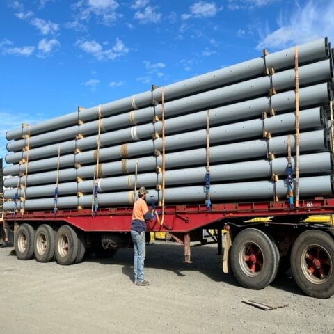


Composite fiberglass utility poles support approved electrical, communication, lighting, camera, antenna, and other equipment above ground. They may be used for private electrical service, utility distribution, telecommunications, roadway and area lighting, commercial properties, industrial sites, campuses, coastal locations, and other infrastructure applications when the exact pole is suitable for the required loading and environment.
Also called fiber-reinforced polymer or FRP poles, composite poles use reinforcing fibers combined with a resin system to form a structural shaft. The fiberglass shaft does not rust and may weigh less than comparable wood or steel poles, depending on the exact length, structural rating, wall construction, and manufacturer.
Available models may include 35-foot to 39-foot light and utility poles and 40-foot to 45-foot light and utility poles. Confirm current availability, total pole length, above-grade height, structural capacity, deflection, embedment, attachment requirements, and manufacturer data before ordering.
Selection Note: Composite utility poles should not be selected by height, material, or a claimed wood-pole equivalent alone. Compare the exact model using its structural rating, mounted equipment, attachment height, wind and ice criteria, allowable deflection, embedment, soil conditions, environmental exposure, and governing project requirements.
How to Select Composite Fiberglass Utility Poles
Start with the intended use, required above-grade height, and all mounted equipment. Then verify the exact pole’s structural capacity and allowable deflection for the attachment arrangement, wind and ice exposure, soil and embedment conditions, environmental exposure, and manufacturer-approved installation and attachment methods.
| Selection Factor | What to Confirm |
|---|---|
| Intended use | Identify whether the pole will support lighting, electrical distribution, communication lines, cameras, antennas, service equipment, or other manufacturer-approved attachments. |
| Total pole length | Confirm the full pole length and distinguish it from the resulting above-grade height after direct-burial embedment. |
| Structural capacity | Review the exact model, allowable or ultimate load, safety factor, ground-line capacity, bending strength, deflection, and manufacturer test data. |
| Wood-pole comparison | If a model is described as comparable to a wood-pole class, confirm the applicable length, loading direction, test method, safety factor, and manufacturer documentation. |
| Mounted equipment | Include conductors, cables, crossarms, fixtures, brackets, cameras, antennas, service equipment, and other approved attachments in the loading review. |
| Attachment height and offset | Confirm where each item will be mounted and how far it extends from the shaft. Higher or offset attachments can increase bending and deflection. |
| Wind and ice exposure | Provide the installation address and applicable project criteria so the complete pole and attachment arrangement can be evaluated for local environmental loading. |
| Deflection limits | Confirm allowable movement for conductors, fixtures, cameras, antennas, and other equipment. A pole may remain structurally intact while moving more than the application permits. |
| Soil and embedment | Review soil conditions, groundwater, drainage, frost, embedment depth, backfill, compaction, ground-line exposure, and slope. |
| Environmental exposure | Identify salt, moisture, chemicals, industrial contaminants, ultraviolet exposure, fire-performance requirements, impacts, and other site conditions. |
| Drilling and attachments | Confirm approved hole locations, fasteners, inserts, brackets, sealing procedures, and field-repair methods with the pole manufacturer. |
| Electrical requirements | Confirm grounding, bonding, wiring, lightning protection, and electrical-clearance requirements for the complete system. A nonconductive shaft does not eliminate these requirements. |
| Delivery and installation | Plan for freight access, unloading, staging, excavation, lifting, rigging, traffic control, and qualified installation personnel. |
Available Heights, Structural Capacity, and Deflection
Composite fiberglass poles may be available in total lengths from approximately 35 feet to 45 feet, depending on the current product line. Because a portion of a direct-burial pole remains below grade, the installed height will be less than the listed total length.
Poles of the same height do not necessarily have the same capacity. Structural performance may vary by manufacturer, shaft diameter, taper, wall construction, fiber orientation, resin system, ground-line location, loading direction, attachment height, and allowable deflection.
Selected composite poles may be designed to provide loading capacity comparable to a specified wood-pole class, but the comparison should be verified for the exact pole length and manufacturer rating. A general statement such as “Class 2 equivalent” does not establish suitability for every installation.
The structural review should include:
- Conductors, communication cables, crossarms, and hardware
- Lighting fixtures, mast arms, brackets, and adapters
- Cameras, antennas, speakers, and other approved attachments
- Attachment height and offset from the shaft
- Wind-exposed area and ice loading when applicable
- Tension, unbalanced loads, and allowable pole-top movement
Lower pole weight may simplify freight and handling, but it does not eliminate the need for qualified rigging, lifting equipment, or safe installation procedures. Do not assume a pole can return to service after an overload, impact, or extreme-deflection event without inspection.
Applications for Composite Utility Poles
Composite utility poles may be considered for several infrastructure and private-site applications when supported by the exact manufacturer data and governing requirements.
- Electrical distribution and private service: May support approved conductors, service equipment, lighting, and related components for utilities, farms, commercial properties, campuses, and industrial sites.
- Communication systems: May support telephone, broadband, fiber, cable, small-cell, antenna, or related attachments when permitted by the manufacturer and pole owner.
- Municipal and private roadway lighting: May support streetlights and street light poles, mast arms, brackets, and wiring where fixture weight, EPA, attachment offset, and wind criteria remain within the pole’s capacity.
- Area and security lighting: May be used for parking areas, yards, commercial properties, utility sites, and other outdoor applications.
- Coastal and marine-adjacent sites: May be considered where salt, spray, humidity, or persistent moisture increase corrosion concerns. Metal hardware and attachments still require corrosion review.
- Transportation facilities: May support approved lighting or equipment at roadway, rail, port, or airport-related sites when agency, clearance, frangibility, and structural requirements are satisfied.
- Industrial environments: May be suitable for selected chemical or corrosive exposures after compatibility with the exact resin system and hardware is confirmed.
Poles intended for lighting, private service, communication, or distribution applications should not be assumed suitable for major transmission structures, cell towers, or specialized transportation systems without project-specific manufacturer approval.
How Composite Fiberglass Poles Are Made
Composite poles combine reinforcing fibers with a resin system to form a structural shaft. Manufacturing methods vary by product and may include filament winding, pultrusion, centrifugal casting, molding, or another proprietary process.
Fiber orientation, resin chemistry, wall construction, taper, curing, ultraviolet protection, and quality controls affect strength, stiffness, deflection, impact resistance, environmental compatibility, drilling procedures, and fire performance.
Use the manufacturer’s drawings, structural tables, test reports, and installation instructions for the exact pole rather than applying general fiberglass characteristics to every model.
Composite Fiberglass Compared with Wood and Steel
| Consideration | Composite Fiberglass Pole Guidance |
|---|---|
| Weight | Composite poles may weigh less than comparable wood or steel poles, which can simplify freight and handling. Confirm the published weight and lifting requirements for the exact model. |
| Corrosion | The fiberglass shaft does not develop red rust. Metal brackets, inserts, fasteners, grounding components, and attachments still require corrosion-resistant materials appropriate for the environment. |
| Decay and insects | Composite shafts are not subject to biological decay or insect damage in the same manner as wood. They still require inspection for impacts, cracking, fiber damage, ultraviolet deterioration, and attachment-related damage. |
| Deflection | Composite poles may deflect differently from wood or steel. Greater flexibility can be acceptable in some applications but unsuitable for equipment requiring limited movement or precise alignment. |
| Field modifications | Drilling, cutting, inserting hardware, or repairing composite material requires manufacturer-approved procedures. Methods used for wood or steel should not automatically be applied to fiberglass. |
| Electrical properties | The fiberglass shaft is generally nonconductive, but metal equipment, wiring, luminaires, brackets, and service components may still require grounding, bonding, and lightning-protection measures. |
| Maintenance | Composite poles may avoid repainting, rust treatment, or preservative retreatment associated with some alternatives. They still require inspection and may require cleaning, hardware replacement, or surface repair. |
| Installed cost | Compare material price, freight, unloading, lifting, embedment, hardware, field modifications, inspection, maintenance, availability, and replacement requirements. |
Composite fiberglass is not automatically the best material for every project. The correct choice depends on loading, allowable deflection, environment, installation conditions, attachment requirements, availability, and total installed cost.
Corrosion, Moisture, Chemical, and UV Exposure
The fiberglass shaft does not rust and may be useful in locations exposed to salt, humidity, irrigation, standing water, or selected industrial contaminants. Suitability still depends on the exact resin system, surface protection, hardware, attachments, temperature, concentration, and exposure duration.
Confirm compatibility with coastal spray, persistent moisture, agricultural chemicals, industrial fumes, acids, alkalis, solvents, deicing materials, ultraviolet radiation, ambient-temperature extremes, and cleaning agents when applicable.
Do not describe composite material as chemically inert or immune to corrosion without reviewing the exact product. The shaft, inserts, fasteners, brackets, and mounted equipment may respond differently to the same environment.
Electrical and Fire-Performance Considerations
The fiberglass shaft is generally nonconductive, but the complete installation may include conductive brackets, fasteners, luminaires, cabinets, conductors, and service equipment. Grounding, bonding, electrical clearances, surge protection, and lightning-protection requirements should be confirmed for the entire system.
Fire behavior varies by resin system, wall construction, additives, coatings, and test standard. If a project has wildfire, flame-spread, ignition, smoke, or self-extinguishing requirements, obtain the exact product’s test data and confirm that it applies to the proposed model.
Do not assume that all composite poles are fireproof, self-extinguishing, or suitable for a designated fire zone based on material type alone.
Direct Burial, Soil, and Drainage
Many composite utility poles are installed by direct burial. A portion of the pole remains below grade and is supported using the manufacturer-specified embedment, backfill, compaction, and drainage procedures.
Installation planning should account for:
- Required above-grade height and embedment
- Soil type and lateral resistance
- Groundwater, drainage, and standing water
- Frost depth and seasonal movement
- Backfill material and compaction
- Slope, erosion, and finished grade
- Underground utilities
- Lifting and installation access
Do not use a generic embedment formula without reviewing the exact pole, soil, loading, manufacturer instructions, and governing project requirements.
Drilling, Attachments, and Field Repair
Composite poles may require factory-installed inserts, field-drilled holes, through-bolts, brackets, crossarms, tenon adapters, or other mounting hardware. These attachments can introduce concentrated loads or expose internal fibers if installed incorrectly.
Before modifying the pole, confirm:
- Approved hole locations, diameters, spacing, and edge distances
- Fasteners, washers, backing plates, inserts, and torque limits
- Required reinforcement and sealing of drilled or cut surfaces
- Restrictions on cutting, grinding, welding, or applying heat
- Grounding and bonding requirements for mounted equipment
Surface or impact damage should be evaluated using the manufacturer’s repair and acceptance procedures. Do not assume that a standard fiberglass repair kit or field patch is appropriate for structural damage.
Delivery and Installation Planning
Composite poles may simplify handling because of their lower weight, but long poles still require planning for freight, unloading, storage, excavation, lifting, and installation.
Before delivery, confirm:
- Complete delivery address and site contact
- Road, gate, turning, and staging access
- Unloading equipment and qualified operators
- Manufacturer-approved lifting points
- Protection from impact or improper stacking
- Ground conditions and installation access
- Traffic-control or site restrictions
Availability depends on the exact height, model, quantity, structural rating, manufacturer, and delivery location. Confirm current stock and freight requirements when requesting a quote.
Inspection and Maintenance
Composite utility poles and their attachments require inspection. Frequency and methods depend on the pole owner, manufacturer, application, environment, mounted equipment, and governing requirements.
Inspection may include:
- Cracking, splitting, fiber exposure, ultraviolet deterioration, or surface damage
- Impact damage or localized crushing
- Leaning, soil settlement, erosion, or washout
- Field-drilled holes, inserts, and repaired areas
- Crossarms, brackets, fasteners, and mounted equipment
- Metal-hardware corrosion
- Grounding and bonding components
- Changes in attachment weight or loading
Composite poles may require less coating or preservative maintenance than some alternatives, but they should not be described as maintenance-free or exempt from routine inspection.
Warranty and Product Documentation
Warranty terms vary by product and manufacturer. Before ordering, confirm the applicable period, covered conditions, exclusions, inspection requirements, approved attachment methods, installation procedures, and claim process.
Useful product documentation may include:
- Dimension, weight, and structural-capacity drawings
- Deflection and wood-pole class comparison data
- Wind, ice, and embedment criteria
- Drilling and attachment guidance
- Fire-performance and chemical-compatibility data when required
- Inspection and repair procedures
How to Compare Composite Utility Pole Quotes and Submittals
When comparing composite utility pole options, verify that each quote addresses the same installation assumptions. A lower-priced pole may represent a different total length, structural rating, deflection limit, embedment condition, attachment configuration, or included hardware package.
- Compare the exact pole model: Confirm manufacturer, total length, shaft dimensions, taper, published weight, and direct-burial configuration.
- Compare the loading basis: Verify the wind, ice, attachment, conductor-tension, and loading-direction assumptions used for each proposed pole.
- Review allowable deflection: Confirm that the proposed pole meets movement limits for the actual lighting, communications, camera, antenna, or conductor application.
- Check included components: Determine whether crossarms, brackets, inserts, fasteners, grounding hardware, tenon adapters, mast arms, or other accessories are included or quoted separately.
- Confirm field-modification requirements: Identify factory-installed holes or inserts and any required manufacturer approval for drilling, mounting, or repairs.
- Review freight and handling: Compare delivery terms, unloading responsibility, lead time, storage requirements, and required lifting equipment.
- Request supporting documentation: Obtain current drawings, structural data, installation instructions, attachment guidance, warranty terms, and environmental documentation relevant to the project.
For utility-owned systems, transportation projects, or installations with specialized attachments, confirm any required approved-vendor status, utility standards, agency specifications, or submittal requirements before ordering.
Need Help Selecting Composite Fiberglass Utility Poles?
LED Lighting Supply can help narrow available composite fiberglass pole options using the project information provided. Useful details include the intended use, installation address, total pole length, required above-grade height, structural or wood-class requirement, mounted equipment, attachment heights, wind and ice criteria, allowable deflection, soil conditions, environmental exposure, quantity, and delivery access.
Contact us about composite fiberglass utility poles and include project drawings, utility requirements, fixture or equipment details, loading information, site photographs, or existing-pole information when available.
LED Lighting Supply can assist with product selection and delivery coordination. Final pole capacity, conductor loading, attachment approval, electrical clearances, grounding, fire performance, embedment, installation, and code requirements should be confirmed by the pole owner, utility, manufacturer, governing authority, and appropriate qualified project professionals.
Composite Fiberglass Utility Poles FAQs
How Should I Select A Composite Fiberglass Utility Pole?
Select the exact pole based on its structural rating, mounted equipment, attachment height, wind and ice criteria, allowable deflection, embedment, soil conditions, environmental exposure, and governing project requirements. Height, material, or a claimed wood-pole equivalent alone do not establish suitability.
Does Listed Pole Length Equal Installed Above-Grade Height?
No. Composite fiberglass poles may be listed by total length, while a portion of a direct-burial pole remains below grade, making the installed above-grade height less than the listed length.
Can Poles Of The Same Height Have Different Structural Capacity?
Yes. Structural performance may vary by manufacturer, shaft diameter, taper, wall construction, fiber orientation, resin system, ground-line location, loading direction, attachment height, and allowable deflection.
What Equipment Should Be Included In The Pole Loading Review?
The loading review should include conductors, communication cables, crossarms, hardware, lighting fixtures, mast arms, brackets, adapters, cameras, antennas, speakers, and other approved attachments. Attachment height, offset, wind-exposed area, ice loading, tension, unbalanced loads, and allowable pole-top movement should also be considered.
Are Composite Fiberglass Utility Poles Suitable For Coastal Or Industrial Sites?
Composite fiberglass poles may be considered for coastal, marine-adjacent, and selected industrial environments, but suitability depends on the exact resin system, surface protection, hardware, attachments, temperature, concentration, and exposure duration. Metal hardware and attachments still require corrosion review.
Can A Nonconductive Fiberglass Shaft Eliminate Electrical System Requirements?
No. The fiberglass shaft is generally nonconductive, but the complete installation may include conductive brackets, fasteners, luminaires, cabinets, conductors, and service equipment that require grounding, bonding, electrical clearances, surge protection, and lightning-protection measures.
What Should Be Confirmed Before Drilling Or Modifying A Composite Pole?
Confirm manufacturer-approved hole locations, diameters, spacing, edge distances, fasteners, washers, backing plates, inserts, torque limits, reinforcement, sealing procedures, and restrictions on cutting, grinding, welding, or applying heat. Improper drilling, cutting, inserts, or repairs can damage the pole or conflict with manufacturer requirements.
Do Composite Fiberglass Utility Poles Require Inspection And Maintenance?
Yes. Composite utility poles and their attachments require inspection, with frequency and methods depending on the pole owner, manufacturer, application, environment, mounted equipment, and governing requirements. They may require less coating or preservative maintenance than some alternatives, but they are not maintenance-free.