


Security Camera Poles
- Rock-solid mounting prevents vibration issues for crystal-clear surveillance footage
- Wind-resistant engineering maintains camera stability during severe weather conditions
- 50+ year corrosion resistance protects your surveillance investment long-term



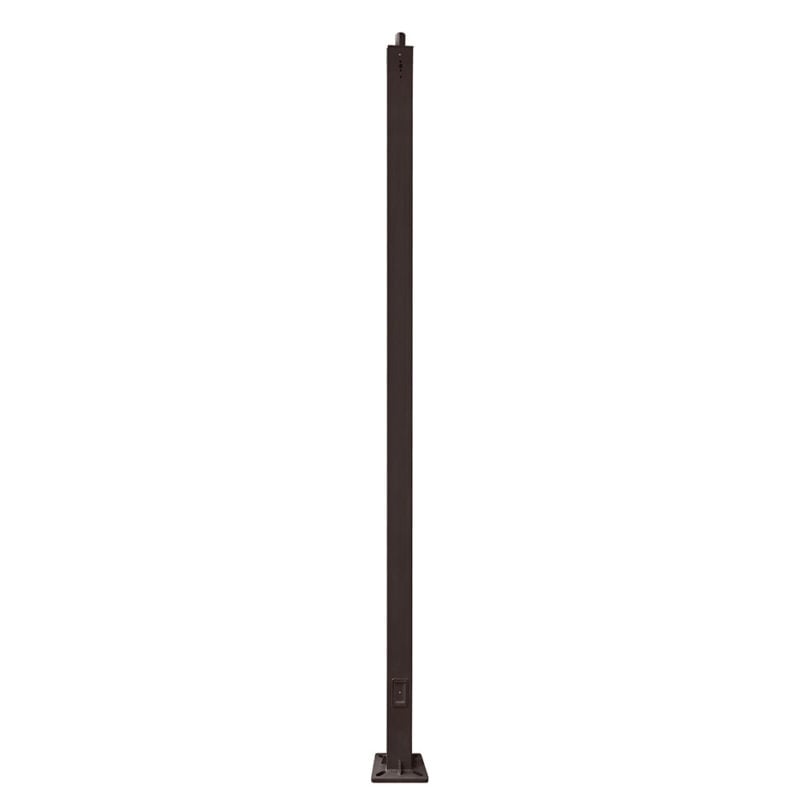
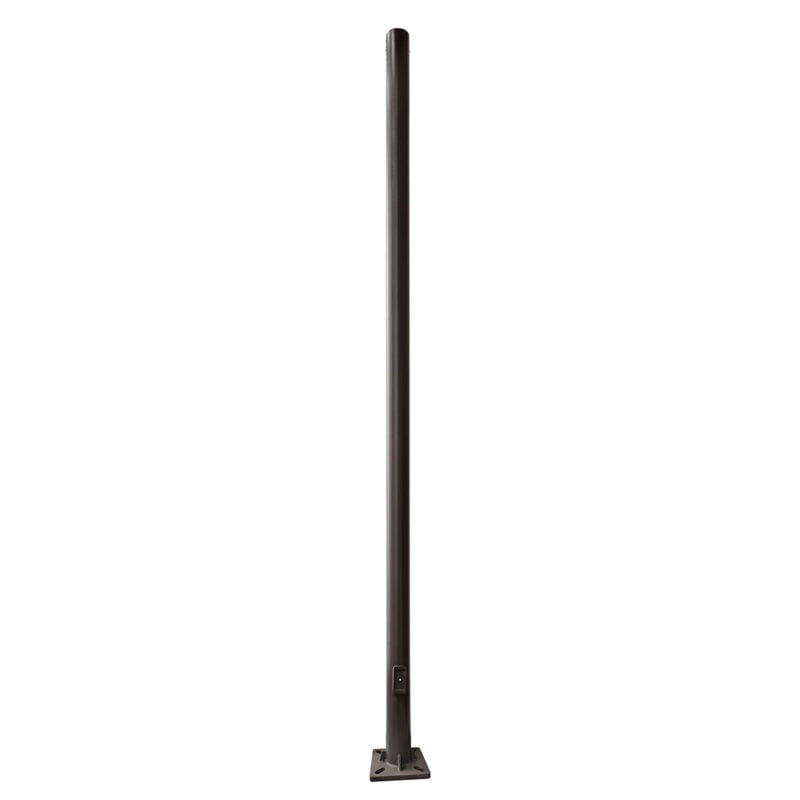
Our Security Camera Poles include steel, composite fiberglass, and wood poles for mounting cameras, wireless equipment, junction boxes, and approved surveillance components. Available configurations include anchor-base and direct-burial installation methods, with mounting options for fixed, pan-tilt-zoom, license plate recognition, and thermal cameras.
These poles are used at commercial properties, industrial facilities, parking areas, schools, municipal sites, equipment yards, entrances, perimeter areas, agricultural sites, and rural properties.
-
 Starting At $527.27
-
Starting At $509.93
-
Starting At $472.73
-
Starting At $2,920.00
-
Starting At $2,920.00
-
Starting At $1,127.27
-
Starting At $1,393.47
-
Starting At $990.91
-
Starting At $1,239.22
-
Starting At $890.91
-
Starting At $1,091.02
-
Starting At $772.73
-
Starting At $912.44
-
Starting At $654.55
-
Starting At $706.07




What Are Security Camera Poles?
Security camera poles provide elevated mounting locations for fixed cameras, pan-tilt-zoom cameras, license plate recognition cameras, thermal cameras, wireless equipment, junction boxes, and other approved surveillance components. They are used at commercial properties, industrial facilities, parking areas, schools, municipal sites, equipment yards, entrances, perimeter areas, and other locations where a building or wall does not provide the required camera position.
Available options include steel poles, composite fiberglass poles, and wood poles. The correct material and pole configuration depend on mounting height, camera quantity, bracket arrangement, total weight, wind-exposed area, allowable deflection, installation method, environmental exposure, cable routing, maintenance access, and site conditions.
Selection Note: Do not select a security camera pole using height or diameter alone. The exact pole, camera, mounting bracket, offset, accessories, foundation or embedment, and project wind requirements must be evaluated as one complete system.
Security Camera Pole Material Options
| Pole Material | General Selection Considerations |
|---|---|
| Steel Security Camera Poles | Steel provides structural stiffness and broad compatibility with camera brackets, tenons, equipment arms, junction boxes, and other approved mounting assemblies. Review the exact pole height, wall construction, shape, finish, allowable loading, deflection, corrosion exposure, and foundation or embedment configuration. |
| Composite Fiberglass Security Camera Poles | Composite fiberglass does not rust and may be useful where salt, irrigation, persistent moisture, fertilizers, chemicals, or other site conditions increase corrosion concerns. Confirm allowable deflection, approved attachment methods, ultraviolet exposure, mounting compatibility, and published structural data for the exact pole. |
| Wood Security Camera Poles | Wood poles are commonly direct buried and may suit utility-style installations, rural properties, equipment yards, agricultural sites, perimeter locations, and selected commercial applications. Confirm species, pole class, preservative treatment, total length, embedment, drilling, attachment methods, camera loading, and wind requirements. |
Material alone does not establish suitability. Compare the exact pole model or class, above-grade height, camera and accessory loading, mounting offsets, wind-exposed area, deflection, installation details, environmental exposure, and maintenance requirements.
How to Select a Security Camera Pole
| Selection Factor | What to Confirm |
|---|---|
| Monitored area | Identify the entrances, parking areas, gates, equipment, buildings, perimeter zones, loading areas, roadways, or other locations the cameras must observe. |
| Camera type | Confirm whether the system uses fixed cameras, PTZ cameras, license plate recognition cameras, thermal cameras, wireless equipment, or a combination of devices. |
| Mounting height | Select the above-grade camera height using the required field of view, nearby obstructions, image-detail goals, camera specifications, maintenance access, property boundaries, privacy considerations, and site layout. |
| Camera arrangement | Confirm the number of cameras, bracket locations, mounting directions, offsets from the pole, junction boxes, wireless antennas, and any other equipment proposed for the pole. |
| Weight and wind exposure | Include the cameras, brackets, arms, adapters, boxes, antennas, cable supports, and other components permitted by the pole manufacturer in the total weight and wind-exposed area. |
| Deflection and image stability | Review the pole manufacturer’s published deflection and structural data, especially for taller poles, PTZ cameras, long mounting arms, high-magnification views, and exposed sites. |
| Project location | Provide the installation address so pole options can be compared with known wind exposure, terrain, frost conditions, soil, salt, moisture, and other environmental factors. |
| Installation method | Determine whether the project requires an anchor-base pole, direct-burial pole, or another manufacturer-approved structural configuration. |
| Foundation or embedment | Confirm soil conditions, drainage, frost depth, groundwater, foundation design, anchor-bolt pattern, embedment, backfill, compaction, and installation-equipment access. |
| Cable routing | Plan conduit, handholes, junction boxes, grounding, bonding, power, low-voltage cabling, network connections, surge protection, and separation from other electrical systems. |
| Maintenance access | Consider how cameras, lenses, housings, brackets, cable connections, antennas, and other equipment will be reached for cleaning, adjustment, repair, or replacement. |
Security Camera Pole Height and Placement
There is no single pole height that works for every surveillance project. The correct height depends on the monitored area, camera type, field of view, required image detail, surrounding obstructions, mounting offset, wind exposure, property boundaries, privacy considerations, and maintenance access.
Lower mounting heights may simplify servicing and provide closer views, but cameras may be more vulnerable to obstruction, tampering, vehicle contact, or limited sight lines. Taller poles may help cameras view over fencing, vehicles, landscaping, equipment, or other obstructions, but they can increase wind response, deflection, foundation demand, installation complexity, and maintenance requirements.
Pole locations should be coordinated with vehicle paths, gates, fences, buildings, trees, signs, overhead lines, underground utilities, property boundaries, pedestrian routes, and the intended camera views. Pole placement should also avoid creating unnecessary blind spots or positioning cameras where future construction or landscaping may obstruct the view.
Camera Weight, Bracket Offset, and Wind-Exposed Area
The pole must support more than the camera body. The complete installed load may include camera housings, brackets, mounting arms, junction boxes, antennas, wireless radios, cable supports, surge-protection equipment, and other approved components.
A camera mounted directly against the pole creates a different structural demand from the same camera installed on a long horizontal arm. Increasing the distance between the equipment and the pole can increase bending and torsional loads, even when the equipment weight remains unchanged.
Effective Projected Area, or EPA, represents the wind-exposed area of mounted equipment. The complete camera and mounting arrangement must remain within the allowable capacity of the exact pole at the required project wind speed. When a camera or accessory manufacturer uses another projected-area or wind-load value, use the published data supplied for that component.
Do not assume a pole is suitable because it has the desired diameter or previously supported a smaller camera. Review the exact pole height, section properties, material, wall construction or pole class, equipment weight, EPA, mounting offset, foundation or embedment, and manufacturer data.
Pole Stiffness, Deflection, and Camera Stability
Security camera performance can be affected by pole movement. Wind, long mounting arms, flexible brackets, loose hardware, foundation movement, and pole deflection may cause temporary image movement or make high-magnification views more difficult to maintain.
Pole stiffness cannot be determined from diameter alone. It also depends on:
- Pole material
- Wall thickness or pole class
- Shape and taper
- Above-grade height
- Camera and bracket weight
- Mounting-arm length and position
- Wind exposure
- Foundation or embedment
- Connection and hardware stiffness
Projects using PTZ cameras, long-range views, license plate recognition cameras, long mounting arms, or exposed locations may require closer review of published pole deflection and camera-manufacturer mounting requirements.
Camera Mounting Brackets and Accessories
Camera poles may use band-mounted brackets, through-bolted brackets, tenon-mounted assemblies, equipment arms, camera platforms, junction boxes, or other manufacturer-approved hardware. The mounting method must be compatible with the exact pole material and construction.
Before selecting or installing mounting hardware, confirm:
- Camera and bracket weight
- Bracket offset from the pole
- Required viewing direction and adjustment range
- Pole shape, taper, and dimensions
- Approved drilling or attachment methods
- Corrosion compatibility between the pole, bracket, and fasteners
- Cable-entry and weather-sealing requirements
- Access for adjustment and future replacement
Do not field-drill, weld, cut, or modify a pole unless the pole manufacturer permits the modification. Unapproved changes can damage protective finishes, weaken the pole, create water-entry points, or affect structural capacity.
Cable Routing, Handholes, and Electrical Coordination
Security camera poles may carry power, low-voltage communication cables, fiber, network wiring, grounding conductors, antenna cables, or other approved services. Cable routing should be planned before the pole, foundation, conduit, and mounting equipment are ordered.
Project planning should confirm:
- Conduit quantity, size, and routing
- Handhole size and location
- Camera cable-entry points
- Junction-box locations
- Power and low-voltage separation
- Grounding and bonding
- Surge protection
- Network, fiber, or wireless connections
- Drainage and weather sealing
- Access for testing and future cable replacement
The complete electrical and communication installation should be reviewed by the appropriate qualified professionals and installed in accordance with applicable project requirements.
Anchor-Base Versus Direct-Burial Security Camera Poles
| Installation Method | Security Camera Pole Considerations |
|---|---|
| Anchor Base | The pole mounts to a concrete foundation using a base plate and anchor bolts. This configuration may simplify future pole replacement when the foundation, anchor bolts, and base pattern remain suitable. Foundation design must account for the exact pole, camera arrangement, wind criteria, soil, and project requirements. |
| Direct Burial | A portion of the pole is embedded below grade. This method is common with wood poles and is available for selected steel and composite fiberglass poles. Embedment, backfill, drainage, soil, ground-line exposure, alignment, and manufacturer requirements must be reviewed for the exact pole and site. |
Neither installation method is automatically stronger, more stable, less expensive, or better for high-wind locations. Selection depends on the pole, loading, soil, drainage, foundation or embedment design, construction access, maintenance plans, and manufacturer requirements.
Foundation, Soil, and Drainage Considerations
Foundation or embedment requirements depend on the exact pole, camera arrangement, equipment offset, wind loading, soil conditions, drainage, frost depth, groundwater, and manufacturer data. Generic foundation details should not be used without reviewing the actual project.
Site planning should account for:
- Soil type and bearing conditions
- Drainage and standing water
- Frost depth and groundwater
- Foundation dimensions and reinforcement when applicable
- Anchor-bolt size, pattern, and projection
- Embedment depth, backfill, and compaction when applicable
- Conduit routing through or around the foundation
- Finished grade and pavement elevations
- Excavation, concrete-truck, crane, and lifting access
- Alignment of cameras and mounting arms with the monitored area
Any pole foundation calculator should be used only for preliminary planning. Final foundation or embedment requirements should be confirmed using the exact pole, loading, soil information, and the appropriate qualified project professionals.
Existing Pole Assessment for Camera Installations
Existing light poles, utility poles, or equipment poles may sometimes be considered for camera mounting, but they should not be assumed suitable based on appearance or available space. Adding a camera, bracket, arm, junction box, antenna, or other equipment changes the loading on the pole.
An existing-pole review should consider:
- Pole material, model or class, age, height, and original design
- Steel corrosion, coating damage, cracking, or base deterioration
- Wood decay, checking, splitting, treatment condition, or ground-line deterioration
- Composite cracking, surface damage, deflection, or attachment damage
- Leaning, movement, impact damage, or foundation settlement
- Base plate, anchor bolts, foundation, or embedded section
- Existing and proposed equipment weight, EPA, and mounting offset
- Compatibility with proposed brackets, arms, boxes, and fasteners
- Available conduit, handholes, grounding, power, and communications
- Maintenance access and future equipment replacement
Do not add cameras or accessories to an existing pole without reviewing the pole condition, manufacturer limitations, structural capacity, mounting method, and foundation or embedment.
Wind, Corrosion, and Environmental Exposure
Security camera poles are often installed in open or elevated areas where wind exposure can be significant. Pole suitability depends on the exact material, height, shape, wall construction or pole class, camera arrangement, bracket offset, wind-exposed area, foundation or embedment, and project wind criteria.
For open-terrain, coastal, hurricane-prone, or other severe-wind locations, review our high-wind rated light poles and verify the complete pole, camera, bracket, foundation or embedment, and site configuration.
Salt, irrigation, standing water, chemicals, fertilizers, deicing products, damaged coatings, soil conditions, and moisture around the base or ground line can affect long-term pole condition. Pole material, preservative treatment, finish, mounting hardware, and fasteners should be selected for the actual environment.
For an initial review of equipment EPA and wind exposure, use our pole wind load calculator. Calculator results are preliminary and do not replace manufacturer structural data, applicable pole-class information, or project-specific engineering when required.
Inspecting and Maintaining Security Camera Poles
Inspect poles, camera brackets, and mounted equipment periodically and after severe weather, vehicle impacts, visible movement, vandalism, or changes to the equipment arrangement. The appropriate inspection interval depends on manufacturer guidance, pole material, site exposure, facility requirements, and the consequences of equipment movement or failure.
Inspection may include:
- Cameras, housings, brackets, arms, adapters, and fasteners
- Base plates, anchor bolts, foundations, or embedded sections
- Corrosion, coating damage, decay, cracking, leaning, or impact damage
- Composite surface or attachment damage
- Wood treatment condition and ground-line deterioration
- Handholes, covers, conduit, cables, grounding, and bonding
- Water entry, damaged seals, or loose junction boxes
- Camera alignment, bracket movement, or unusual vibration
- Drainage, standing water, soil erosion, and settlement
- Changes in camera quantity, weight, bracket offset, or wind-exposed area
Follow the pole, camera, bracket, and equipment manufacturers’ inspection and maintenance instructions. Do not add cameras, antennas, lights, signs, boxes, or other components unless the exact pole manufacturer permits the attachment and the resulting loading has been reviewed.
Common Security Camera Pole Selection Mistakes
- Selecting by pole diameter alone: Diameter does not establish stiffness or capacity without considering material, wall thickness or pole class, height, loading, wind, and foundation conditions.
- Choosing height before defining the camera view: Mounting height should coordinate with the monitored area, camera specifications, image-detail goals, obstructions, property boundaries, privacy considerations, and maintenance access.
- Ignoring bracket offset: A camera mounted on a long arm can create greater structural demand than the same camera mounted close to the pole.
- Overlooking deflection: Pole movement can affect high-magnification, PTZ, and license plate recognition camera performance.
- Ignoring total mounted equipment: Cameras, brackets, boxes, antennas, adapters, and cable supports all contribute to weight and wind exposure.
- Adding lighting without structural review: A pole selected for cameras may not have capacity for additional fixtures, crossarms, or other equipment.
- Field-drilling without approval: Unapproved holes or modifications may damage protective finishes or affect structural capacity.
- Using generic foundation details: Soil, wind, pole height, camera loading, bracket offset, drainage, and manufacturer requirements affect the foundation or embedment.
- Assuming anchor base is automatically more stable: Stability depends on the complete pole, loading, foundation or embedment, soil, and site configuration.
- Reusing an existing pole without evaluation: Condition, loading, foundation, attachments, wiring, and manufacturer limitations should be reviewed before adding equipment.
- Forgetting cable and handhole requirements: Power, communications, grounding, surge protection, and maintenance access should be planned before ordering.
- Ignoring future maintenance: Camera cleaning, aiming, replacement, and cable access become more difficult as pole height and equipment complexity increase.
Need Help Selecting a Security Camera Pole?
LED Lighting Supply can help narrow wood, steel, and composite fiberglass pole options based on the project information provided. Useful details include the installation address, monitored area, required mounting height, camera type and quantity, camera and bracket weights, mounting-arm dimensions, proposed accessories, cable requirements, installation method, existing pole information, nearby obstructions, property boundaries, privacy considerations, and maintenance access.
Contact us about security camera poles and include a site plan, aerial image, camera data sheets, bracket drawings, equipment weights, proposed pole locations, or existing pole information when available. Final structural, foundation, embedment, electrical, communication, installation, and code requirements should be confirmed by the appropriate qualified professionals for the project.
Security Camera Poles FAQs
How Should I Select The Right Security Camera Pole?
Select a security camera pole by evaluating the complete system, including the exact pole, camera type and quantity, brackets, offsets, accessories, wind-exposed area, foundation or embedment, cable routing, maintenance access, and site conditions. Height or diameter alone does not establish suitability.
How Do I Choose The Right Camera Pole Height And Location?
Choose pole height and placement based on the monitored area, camera type, field of view, image-detail goals, obstructions, mounting offset, wind exposure, property boundaries, privacy considerations, and maintenance access. Coordinate pole locations with vehicle paths, gates, fences, buildings, trees, signs, utilities, pedestrian routes, and intended camera views.
What Should Be Included In Camera Pole Loading?
Camera pole loading should include cameras, housings, brackets, mounting arms, junction boxes, antennas, wireless radios, cable supports, surge-protection equipment, and other approved components. The complete arrangement must remain within the allowable capacity of the exact pole at the required project wind speed.
Why Does Bracket Offset Matter When Selecting A Camera Pole?
Bracket offset matters because increasing the distance between equipment and the pole can increase bending and torsional loads, even when the equipment weight remains unchanged. A camera mounted directly against the pole creates a different structural demand from the same camera mounted on a long horizontal arm.
How Do Steel, Composite Fiberglass, And Wood Camera Poles Differ?
Steel provides structural stiffness and broad compatibility with approved camera mounting assemblies, composite fiberglass does not rust and may be useful where corrosion concerns are increased, and wood poles are commonly direct buried and may suit utility-style, rural, equipment-yard, agricultural, perimeter, and selected commercial installations. Material alone does not establish suitability, so the exact pole model or class, loading, deflection, installation details, environmental exposure, and maintenance requirements should also be compared.
Should I Choose An Anchor-Base Or Direct-Burial Security Camera Pole?
Choose an anchor-base or direct-burial security camera pole based on the exact pole, loading, soil, drainage, foundation or embedment design, construction access, maintenance plans, and manufacturer requirements. Anchor-base poles mount to concrete foundations with base plates and anchor bolts, while direct-burial poles have a portion embedded below grade and are common with wood poles and available for selected steel and composite fiberglass poles.
Can An Existing Pole Be Used For A Security Camera?
An existing light pole, utility pole, or equipment pole may sometimes be considered for camera mounting, but it should not be assumed suitable based on appearance or available space. Review the pole condition, manufacturer limitations, structural capacity, mounting method, foundation or embedment, and the existing and proposed equipment weight, EPA, and mounting offset before adding equipment.