Do Dimmer Switches Save Power?
What is a Dimmer Switch?
Dimmer switches and lighting controls allow users to adjust the light output of compatible fixtures, giving commercial and industrial facilities greater control over illumination levels. This can help avoid operating an area at full output when lower light levels are appropriate or when the space is unoccupied.
Smart dimming controls can reduce lighting energy use while supporting lighting levels appropriate for different tasks, schedules, and occupancy conditions. The key question many facility managers ask is: do dimmer switches actually save energy?
When Should You Use Dimmer Switches?
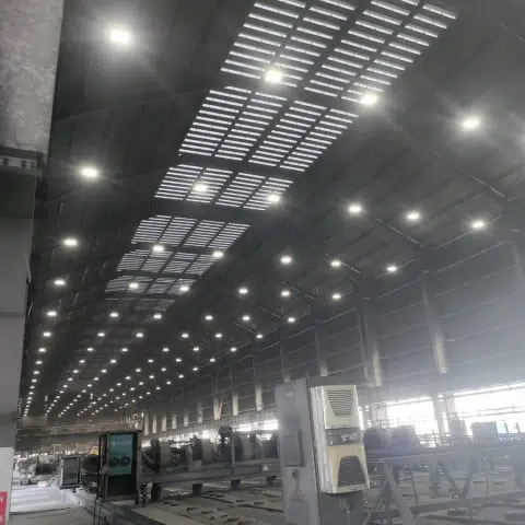
Dimming systems can be useful in facilities with variable occupancy, daylight availability, or changing lighting needs. Some spaces may require consistent lighting levels for operational, safety, security, or task-visibility reasons, such as:
- 24/7 manufacturing facilities
- Airport terminals and concourses
- Hospital patient areas and emergency zones
- Critical security monitoring areas
Even in these applications, compatible controls may be used where permitted and where lighting levels remain appropriate for the task and applicable code requirements. Facilities with variable schedules, such as schools, offices, and warehouses with shift operations, can often benefit from properly designed dimming controls.
Do Dimmer Switches Save Energy?
Yes. Compatible LED dimming systems generally reduce energy consumption when light output is reduced. Dimming to approximately 50% light output may reduce input power by roughly 40% to 50%, but the actual relationship depends on the LED driver, fixture, dimming method, and control settings.
Modern LED drivers regulate power to produce the requested light level. Dimming can reduce energy use with LEDs as well as other dimmable lighting technologies; actual savings should be based on the fixture’s published dimming and input-power data.
Types of Commercial Dimming Systems
Phase-Cut (Triac) Dimming: Common in residential applications and some smaller commercial fixtures. Phase-cut dimmers control the portion of each AC waveform delivered to a compatible load. They can work well with compatible LED fixtures, but LED compatibility, minimum load, dimming range, and flicker performance vary by dimmer and driver.
0-10V Dimming: A widely used analog control method for commercial LED fixtures, including fixtures used in warehouses, manufacturing areas, and parking lots. It uses a low-voltage control signal and requires compatible drivers and controls.
Benefits of LED Dimming Systems
Installing compatible dimming controls can offer several advantages for commercial facilities:
- Energy Cost Reduction: Lower light levels generally reduce fixture input power.
- Potentially Reduced Operating Stress: Lower drive levels may reduce thermal stress in some systems, though fixture life depends on driver design, thermal conditions, operating environment, and other factors.
- Improved Visual Comfort: Appropriate light levels and control zoning can help manage glare and visual comfort when fixture placement and optics are properly designed.
- Operational Flexibility: Controls can adapt lighting to different tasks, schedules, daylight conditions, and occupancy levels.
LED fixtures are generally more energy efficient than many traditional lighting technologies. Adding properly selected controls can further reduce lighting energy use where reduced output is appropriate.
Professional lighting design is important for dimming-system success. Consider using a photometric lighting plan to evaluate fixture placement, lighting levels, control zones, and dimming settings for your specific application.
Understanding 0-10V Dimming Systems
0-10V dimming uses a low-voltage DC control signal to communicate a requested dimming level to compatible LED drivers. In many systems, a higher control voltage corresponds to higher light output and a lower voltage corresponds to lower output. Exact dimming response, minimum output, and off behavior are determined by the driver and control specifications.
- 10V signal: Typically corresponds to maximum or near-maximum light output.
- Intermediate signal: Requests an intermediate light level; the relationship between control voltage, light output, and input power may not be perfectly linear.
- Low-end signal: Typically corresponds to the driver’s programmed or rated minimum dimming level.
- 0V signal: May command off or minimum output depending on the driver and control system. Verify the fixture driver’s published specifications.
0-10V vs. 1-10V Dimming
The terms 0-10V and 1-10V are often used inconsistently in the market, so the fixture driver and control documentation should always be reviewed.
In a typical 1-10V system, the control signal adjusts light output between a high level and a specified minimum level, often near 10% output. The control signal generally does not switch the fixture off; a separate switched line-voltage control, relay, or compatible digital control system may be needed for off operation.
With 0-10V LED drivers, a 0V control signal may command off on some models, while other drivers remain at a minimum dim level or require a separate switching device to turn off. Do not assume that every 0-10V fixture will turn off at 0V.
Lighting on emergency egress routes, in designated emergency areas, or in other code-regulated applications must be designed and controlled in accordance with applicable electrical, building, fire, and life-safety requirements. Controls should not reduce required illumination below applicable levels.
Occupancy sensors can be used with compatible 0-10V or 1-10V controls to raise lighting to an occupied level and reduce it to a programmed unoccupied level after a delay. Available high-end trim, low-end dimming level, timeout, and off functions vary by sensor, driver, and control system.
0-10V Dimming System Components
Note: Electrical work should be performed by qualified electricians in accordance with applicable codes, manufacturer instructions, and local requirements. This information is provided for planning purposes only.
Required Components
- Compatible LED fixtures with 0-10V or 1-10V dimmable drivers, as required by the selected control system
- Compatible wall dimmers, sensors, or control devices rated for the connected drivers and control method
- Control wiring: Wire type, conductor size, shielding, polarity, routing, and maximum control-circuit length should follow the control and driver manufacturer instructions and applicable code.
- Line-voltage wiring: Conductor size and wiring method must be selected for the circuit load, overcurrent protection, installation conditions, and applicable electrical code.
System Overview
A typical 0-10V dimming installation includes line-voltage wiring to power the fixtures and separate low-voltage control conductors to communicate the requested dimming level to each compatible driver. Fixture voltage may be 120V, 277V, or another listed input voltage depending on the product. The control wiring does not replace the branch-circuit wiring that powers the luminaires.
Professional installation and commissioning help confirm wiring, control compatibility, dimming range, occupancy settings, and code compliance. A photometric lighting plan can help evaluate dimming zones and control locations for a specific facility.
Installation Planning
Successful dimming system installation requires:
- A detailed lighting plan showing fixture and control zones
- Fixture drivers, dimmers, sensors, and control equipment that are listed and documented as compatible
- Code-compliant electrical installation based on the project conditions
- System commissioning and testing, including verification of minimum levels and any required emergency-lighting operation
Safety Notice: Always turn off power at the circuit breaker and verify circuits are de-energized before beginning electrical work. Use appropriate safety equipment, including secure ladders, safety harnesses, and fall protection for elevated installations. Consult applicable codes and use qualified electricians for installation and commissioning.